Preflight Checklist - Truck Launch
Swift GCS includes an integrated preflight checklist, replacing paper checklists. Some steps are automated, while others require manual interaction. Each step in the GCS has an info button for help text. This manual section mirrors the GCS checklist and offers supplementary information.
Always adhere to the aircraft Performance and System Limitations.
Adherence to the preflight checklist is crucial to the safe and successful operation of the aircraft. The preflight steps must be performed before every flight. Failure to preform a preflight step can result in a total loss of the aircraft and pose a hazard to people on the ground.
Contents
- Launcher - Assemble
- Aircraft - Assemble
- Aircraft - Inspect
- Pitot Tube - Extend
- Propeller - Torque
- Avionics Battery - Install
- Aircraft - Fuel
- Weight and Balance - Verify
- Voice Radio - Check
- Telemetry Radio USB - Connect
- Hand Controller - On
- Avionics Battery - Connect
- Aircraft Hatches - Secure
- Autopilot - Connect
- Firmware - Check
- Parameters - Check
- Old Mission - Clear
- Mission - Create
- Rally Points - Add
- Mission - Upload
- Flight Modes - Verify
- Failsafes - Verify
- Autopilot - Warmup
- Airspeed - Calibrate
- Compass - Check
- Mode - Manual
- Control Surfaces - Enable
- Manual Control - Check
- Mode - FBWA
- FBW Response - Check
- Mode - Manual
- Release - Power On
- Launcher - Mount Aircraft
- Release - Test
- Release Hook - Secure
- Release Tension - Set 10 lbs
- No Warnings - Verify
- Engine - Prime
- Aircraft - Arm
- Ignition - On
- Engine - Start
- Engine - Warmup
- Full Throttle RPM - Verify
- Idle RPM - Verify
- Launcher - Raise
- Launcher Pins - Install
- Truck - Taxi to Runway
- Takeoff Heading - Establish
- Release Tension - Verify 10 lbs
- No Warnings - Verify
- Begin Takeoff - Announce
- Throttle 75% - Raise at 50 mph
- Pitch Up 75% - Hold at 50 mph
- Takeoff Speed - Establish 75 mph
- Aircraft - Release
- Aircraft Clear - Announce
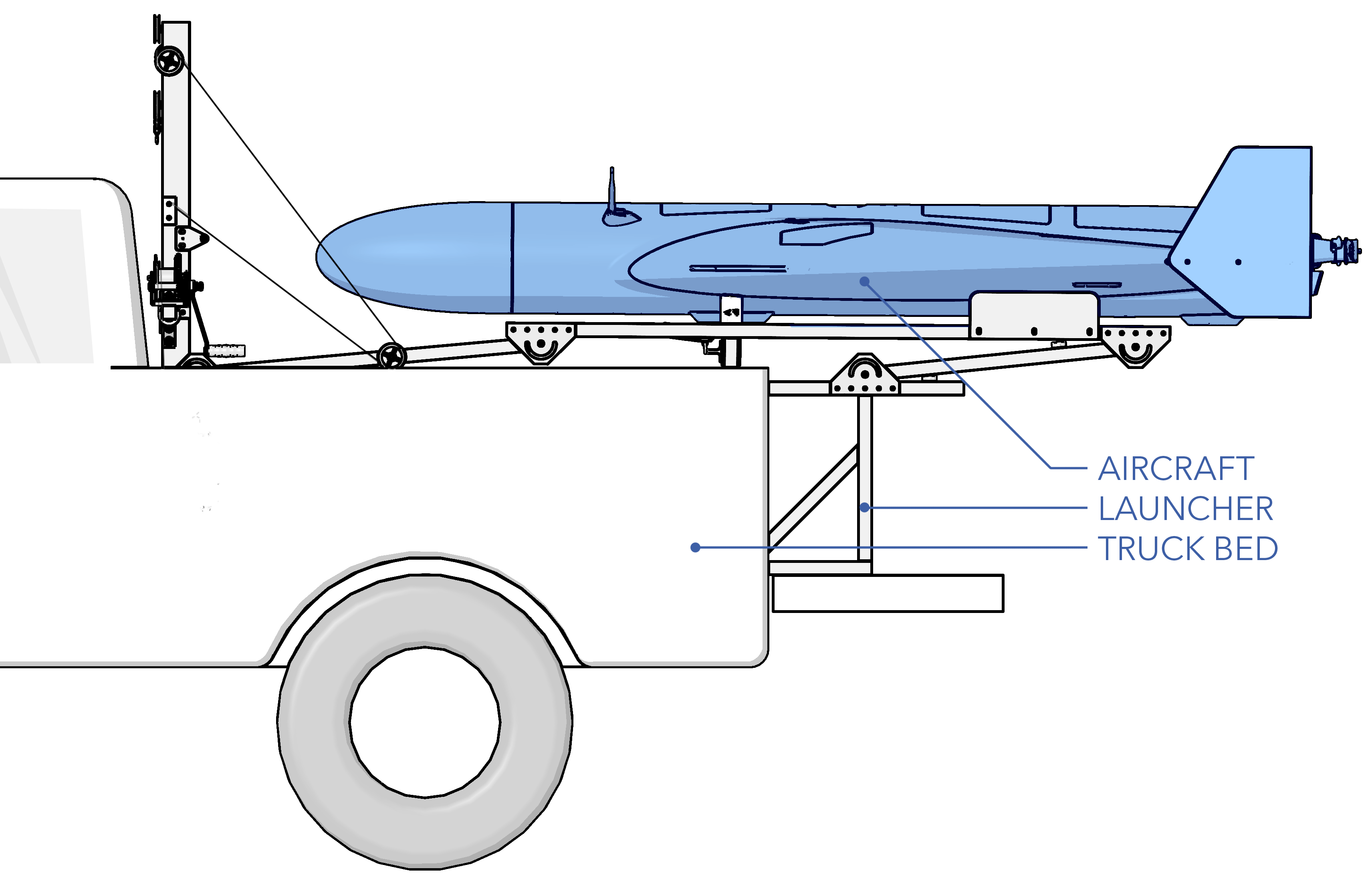
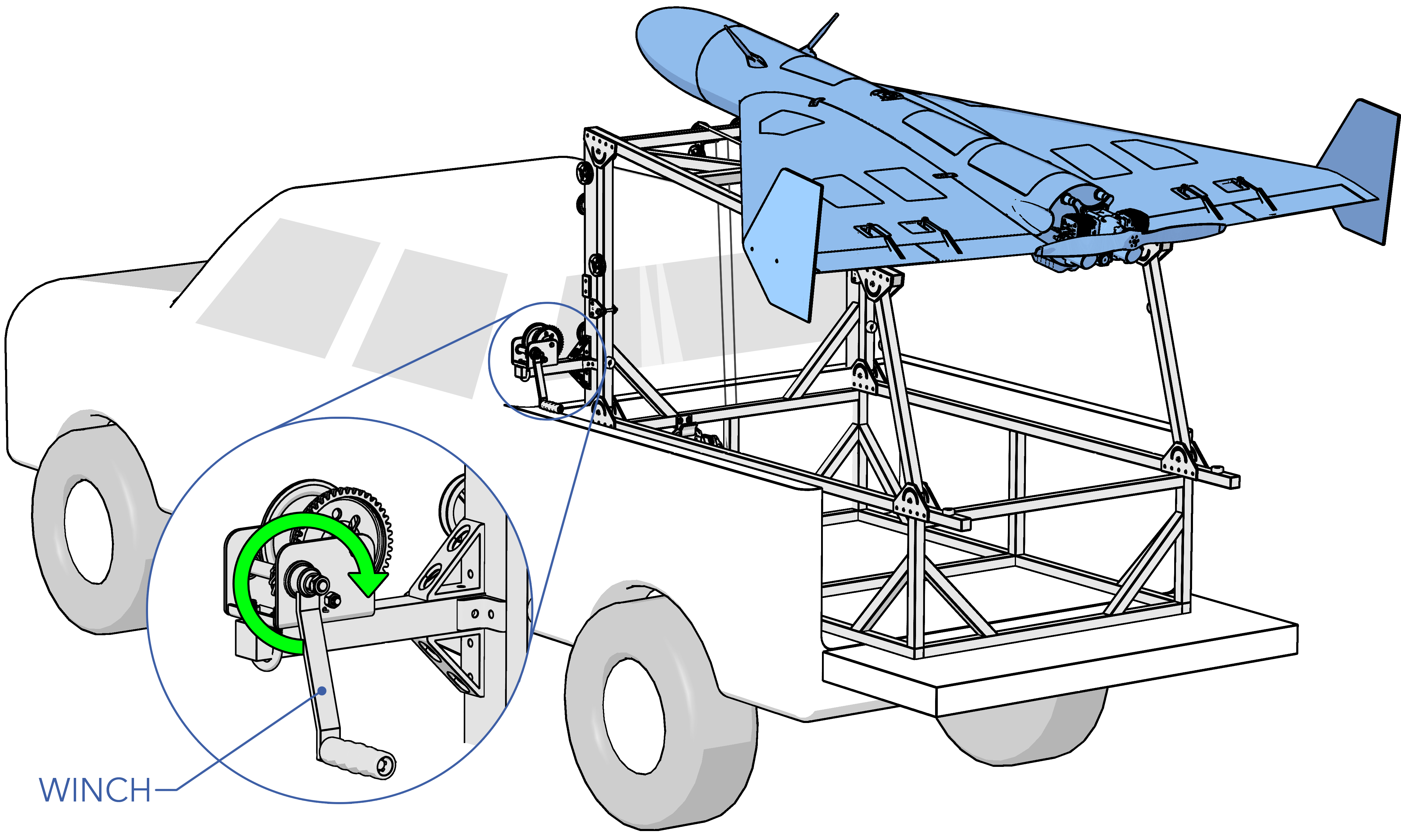
Launcher - Assemble
Place the launcher in the truck bed and slide it forward until the front bumpers on the launcher touch the truck. Secure the launcher to the truck bed using four ratchets straps, one in each corner of the launcher as shown below. Ensure the ratchet strap placement does not prevent the launcher from raising or lowering smoothly.
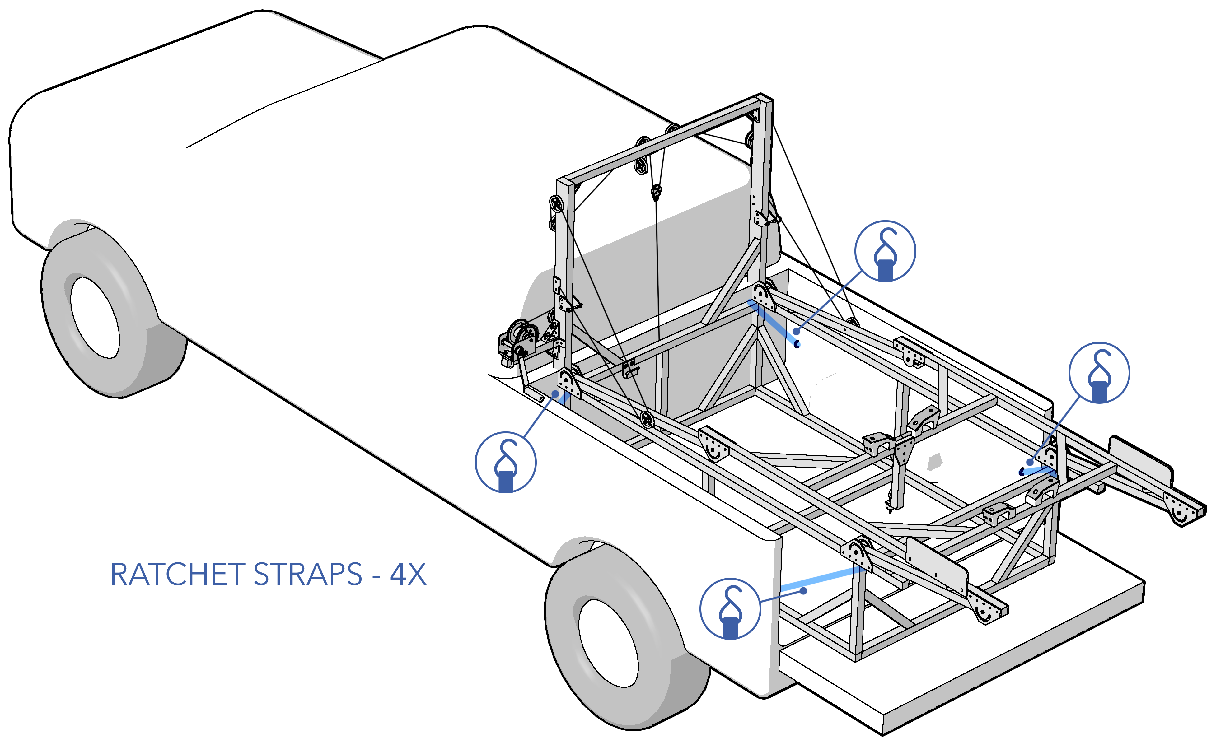
Lifting the launcher requires a minimum of two people.
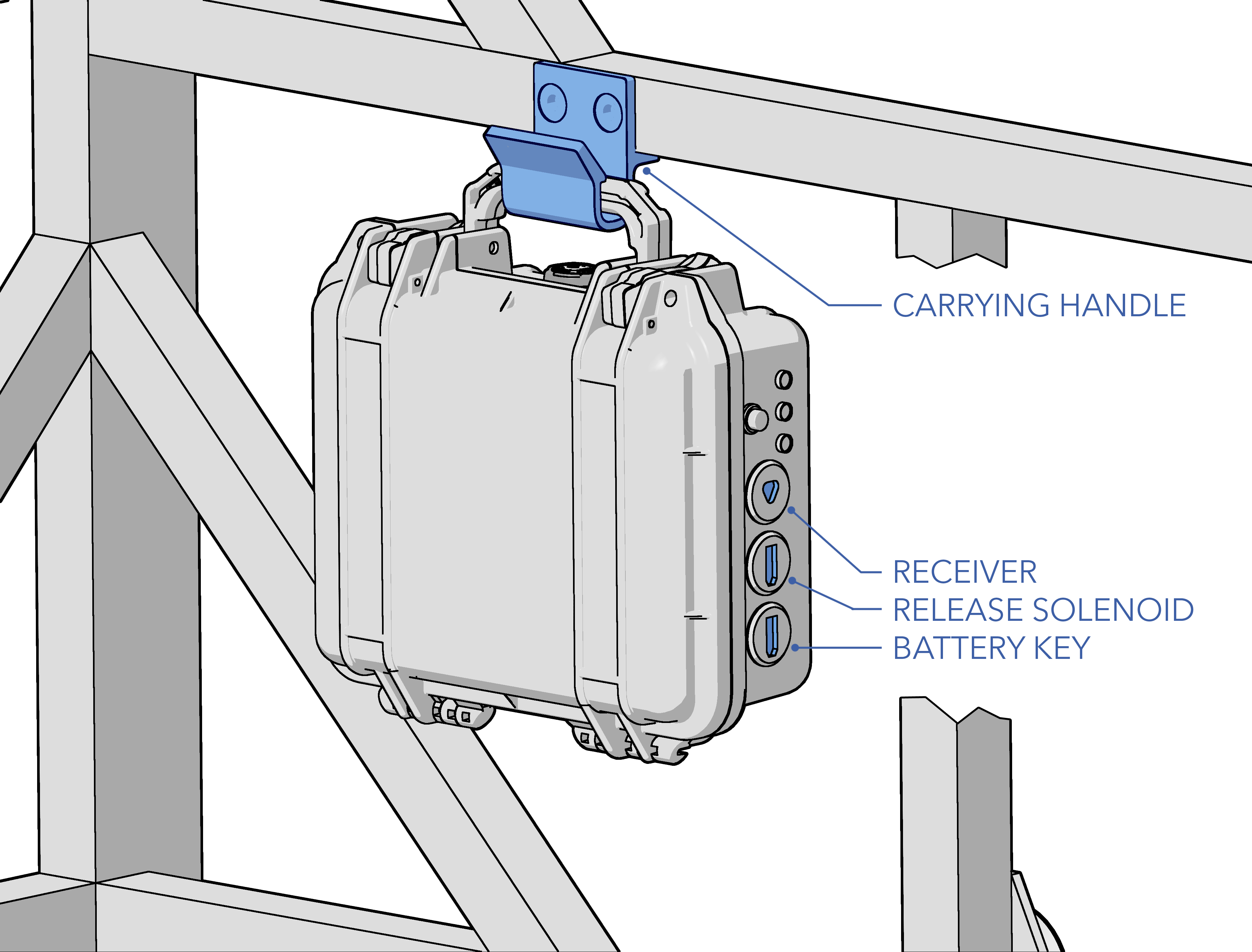
With the launcher secured, attach the release box using the carrying handle. Connect the receiver, release solenoid, and battery key to the release box. Attach the release shackle and line scale to the eye bolt, allowing them to hang for now.
Aircraft - Assemble
Remove the aircraft from its transport case and assemble the aircraft on its stand using the following walkthrough.
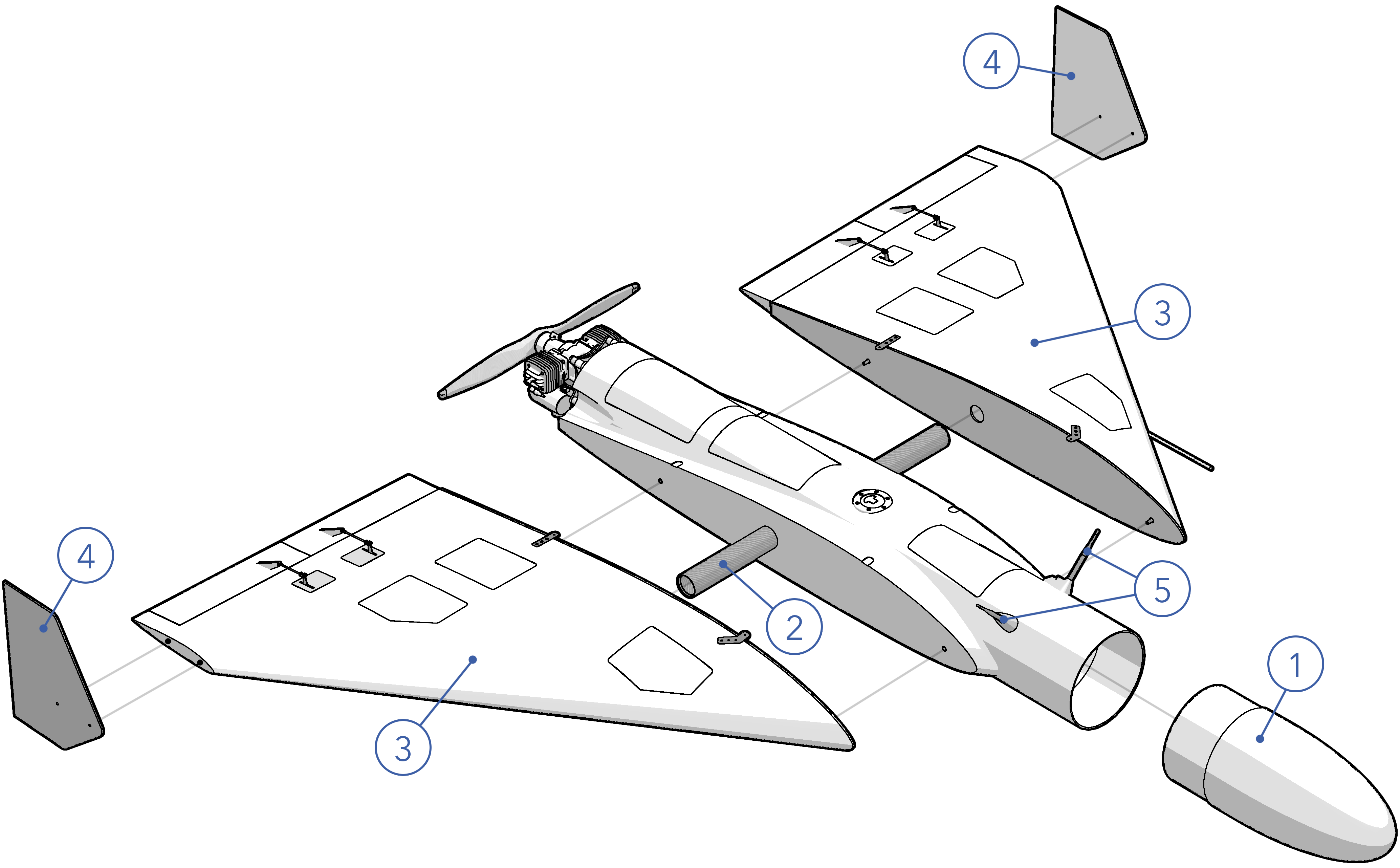
- Nose Cone: Install the nose cone and secure it with three nose cone screws. The top is marked with the serial number and alignment indicator.
- Wing Spar: Slide the wing spar into the fuselage.
- Wings: Slide each wing over the spar, leaving a small gap between the wing and fuselage. Connect the wing-to-fuselage connector, then slide the wing fully into place taking care not to pinch any wires. Secure each wing with two wing screws.
- Wing Fences: Attach and secure each wing fence using two screws. Each fence is marked with a serial number that should face outward and upright when properly installed.
- Antennas: Unfold the telemetry radio antennas.
Assembly of the aircraft requires a minimum of two people.
Aircraft - Inspect
Assemble the aircraft and inspect for any damage and/or irregularities to the airframe, payload, and subcomponents while assembling. Damage may have been caused by previous flights, maintenance, transportation, environmental, or from normal wear and tear. Refer to the Maintenance Section for a more detailed inspection procedure or if damage is found.
- Airframe: Inspect the fuselage, nose cone, wings, and wing fences for cracks or fractures in the composite structure.
- Control Surfaces: Inspect the composite control surface hinges for buckling, cracks, or tears. Check the servo linkages and control horns for damage and ensure they are securely mounted. Slowly move each control surface through their range of motion, ensuring the servo operates smoothly without hitching or skipping.
- Landing Skids: Ensure each landing skid is present, securely attached, no missing screws, and has adequate wear material remaining.
- Antennas: Verify all radio, GPS, and payload antennas (if applicable) are secure.
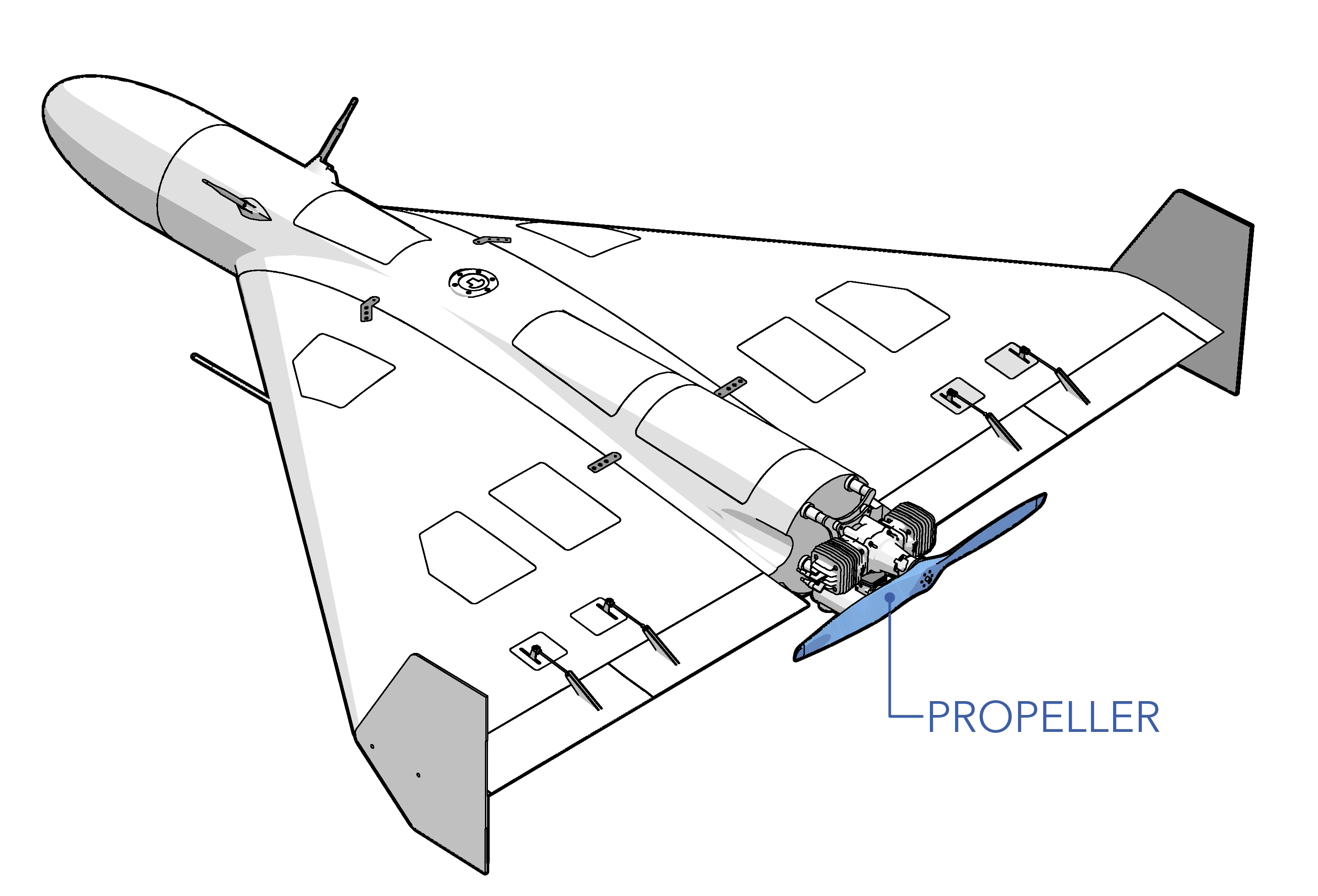
- Propeller: Inspect the propeller for cracks, chips, fractures, etc. Ensure all propeller screws are present. Ensure the propeller is facing the correct way and not reverse.
- Engine Vibration Mounts: Firmly grasp the engine and wiggle it in all directions. The rubber engine mounts should flex but resist excessive movement. Visually check for cracks, missing pieces, or if any mounts are sheared off.
- Engine Standoffs: Firmly grasp each engine vibration mount standoff and ensure it is secure. No twisting or rocking should occur.
- Mufflers: Torque the four muffler bolts to 70 in/lbs. Firmly grasp each muffler and wiggle it in all directions to ensure both are securely attached to the engine. Verify the gasket between each muffler and the engine is present and intact with minimal signs of an exhaust leak.
- Spark Plug Caps: Ensure both spark plug caps are secure.
- Throttle Linkage: Inspect the throttle servo and linkage for damage and mounting security. Slowly move the throttle servo through its full range of motion, ensuring the servo operates smoothly without hitching or skipping.
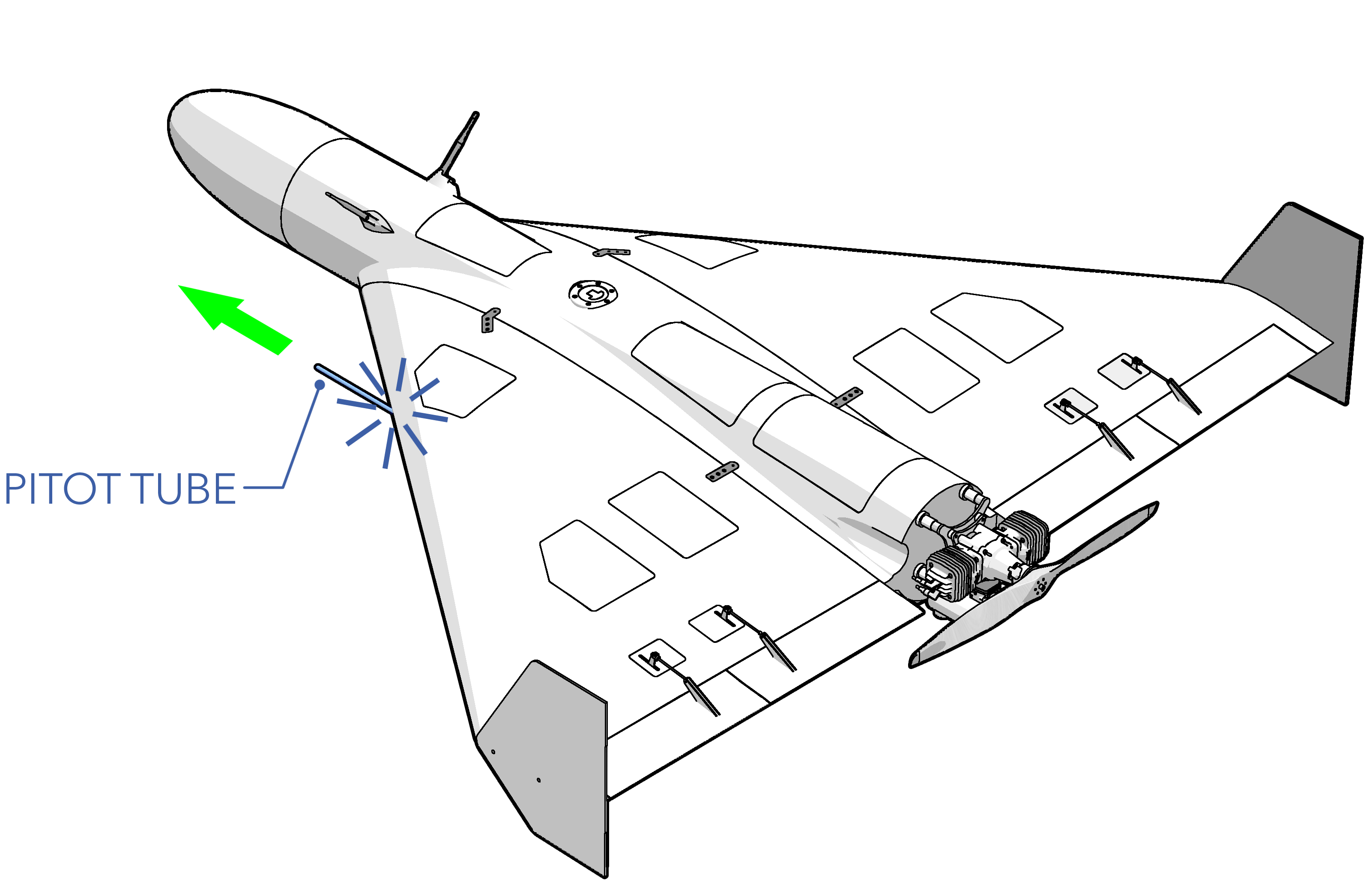
Pitot Tube - Extend
Extend the pitot tube until it snaps into place. Verify that the pitot is not bent and free of obstructions. Verify that the pitot tubing in the fuselage is free of kinks. Verify that the hoses are fully inserted into the backside of the pitot tube itself and the airspeed sensor.
Propeller - Torque
Gradually torque the propeller bolts to 90 in/lbs in a star pattern.
Avionics Battery - Install
Install and the avionics battery within the fuselage and secure it down using the Velcro straps.
Aircraft - Fuel
Fuel the aircraft with the appropriate amount of gasoline needed for the flight, including a 30 minute reserve of 6 lbs (1 gal). Refer to the Fueling Section for detailed fueling and mixing instructions.
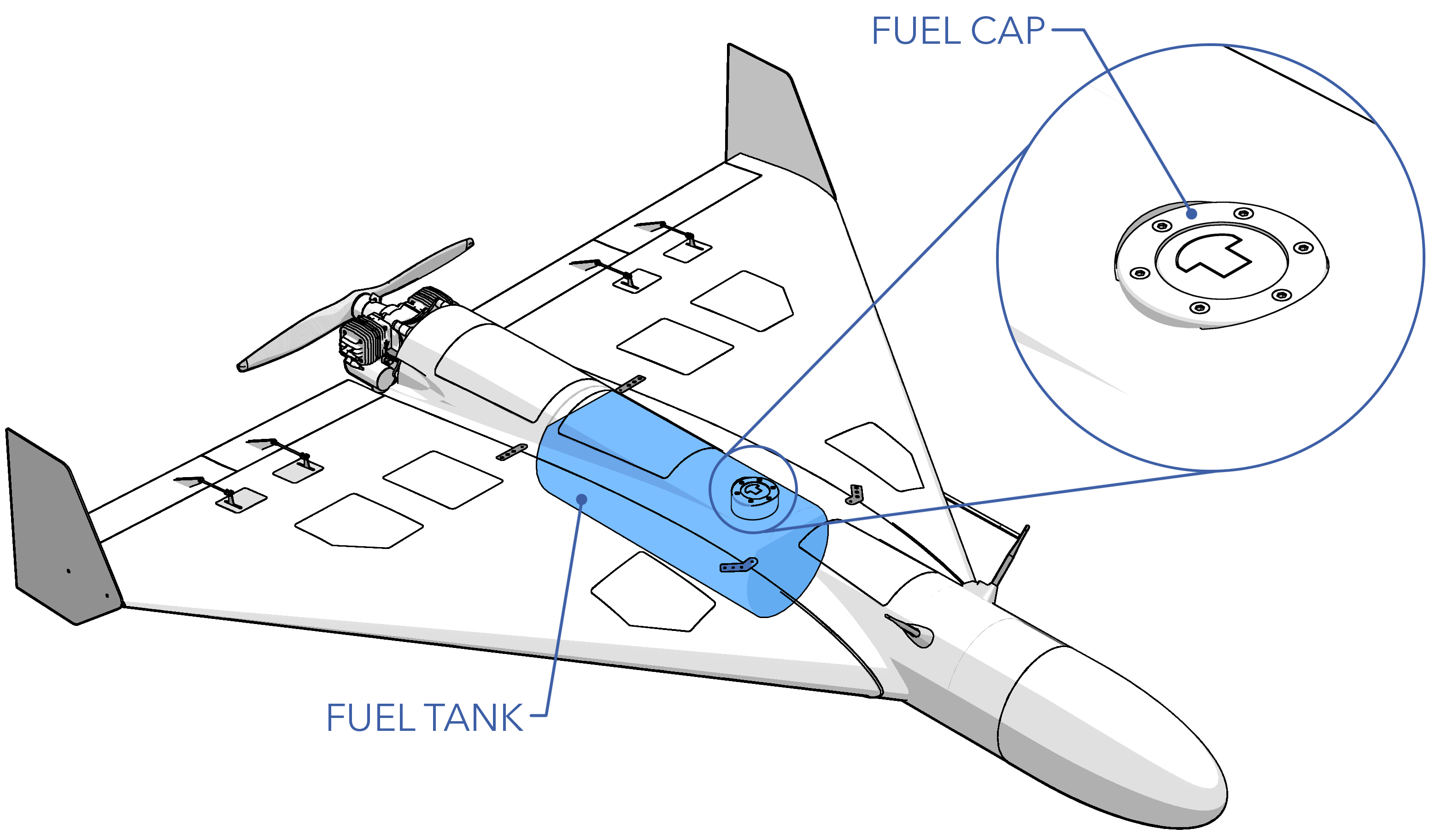
The aircraft burns fuel at approximately ~12 lbs/hr (2 gal/hr)
Weight and Balance - Verify
Verify that the aircraft with payload and ballast is balanced at the 20% CG mark and that the MTOW does not exceed 180 lbs.
Refer to the Weight and Balance Section for detailed balancing instructions.
COM Radio - Check
Power on and test each voice radio. The number of radios may vary based on the site setup, but a communication link between the operator and driver is always required.
Telemetry Radio USB - Connect
Connect the telemetry radio USB to the GCS computer.
Hand Controller - On
Power on the hand controller. Ensure the correct model is displayed.
Avionics Battery - Connect
Connect the avionics battery.
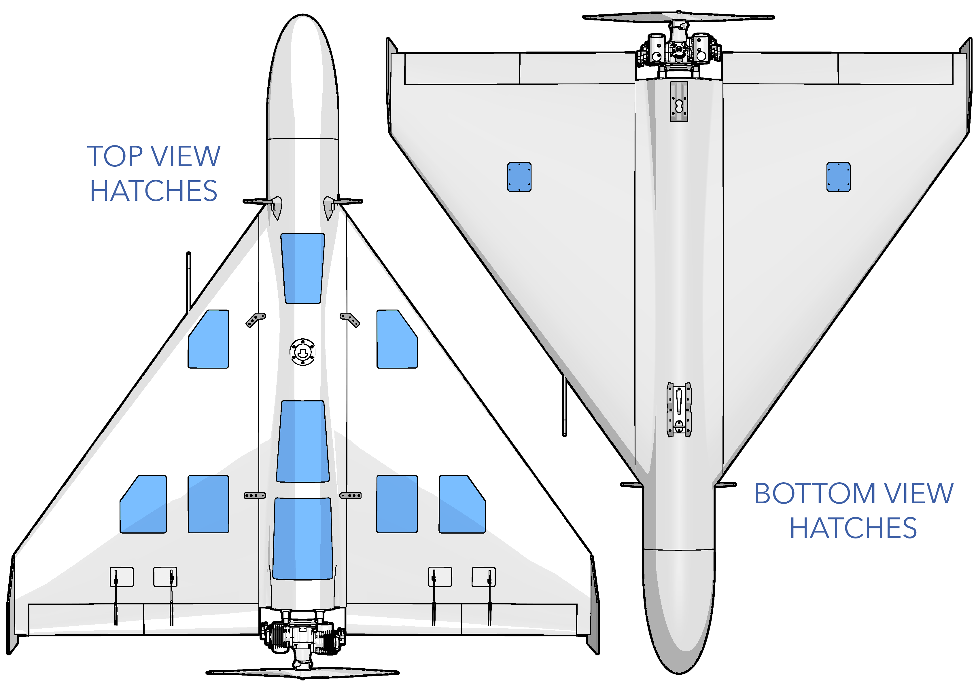
Aircraft Hatches - Secure
Ensure all aircraft hatches are secured.
Autopilot - Connect
From the Checklist tab in Swift GCS press Connect ⇨ Port: COM# ⇨ Baud 57600
Firmware - Check
The GCS will automatically check that the autopilot's firmware is correct and up to date. If this check fails, go to the Settings Tab ⇨ Firmware Upload in Swift GCS to update the firmware.
Refer to firmware update for more information.
Parameters - Check
The GCS will automatically check that the autopilot parameters are correctly configured. If any parameters fail the check please contact info@spektreworks.com. Do not fly.
Old Mission - Clear
The existing mission on the aircraft must be cleared before a new flight. Press the Clear button on the checklist step or go to the Plan Tab ⇨ Clear WP ⇨ Clear mission on the aircraft.
Mission - Create
Create or load a mission from the Plan Tab.
Refer to mission planning for more information on waypoints.
The aircraft will climb or descend enroute between waypoints. The autopilot calculates a slope between two waypoints and plans to achieve its altitude as it reaches the next waypoint. For example, if your next waypoint is one mile away and 1,000 feet higher, the aircraft will gradually climb along that one mile route. The aircraft will not fly to a waypoint and then climb or descend in circles.
Rally Points - Add
From the Plan tab ⇨ Add ⇨ Rally to insert a rally point.
Mission - Upload
Press Upload on the checklist step, or go to the Plan Tab ⇨ Upload to upload the mission to the autopilot.
Planned and modified waypoints will appear red in the GCS until uploaded to the autopilot.
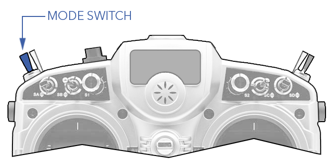
Flight Modes - Verify
Navigate to the Settings Tab ⇨ Flight Modes to choose which flight modes are mapped to the hand controller's mode switch. You must save your changes for the new configuration to take effect. Typically the three modes are manual, FBWA, and auto, however this can vary depending on the mission requirements and crew experience. The modes chosen here do not limit which modes are available through the GCS, just the hand controller.
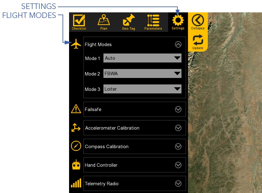
The current flight mode is displayed on the top status bar in the GCS.
Failsafes - Verify
Navigate to the Settings Tab ⇨ Failsafes to configure your failsafes.
Autopilot - Warmup
The autopilot has an internal heater to hold the IMU at a specific temperature which improves the accuracy of the sensors. Please wait for the IMU to reach the required temperature before proceeding.
Airspeed - Calibrate
This step will walk you through calibrating the airspeed sensor. First shield the pitot tube from any wind with the provided pitot tube cover. Next, press Calibrate on the Checklist Tab. Remove the pitot tube cover before testing. To conduct the test first cover the drain port with your fingertip. Next, tap and hold the pitot tube opening with your other fingertip while someone monitors the GCS. This action will trap air, increasing the sensor pressure reading. If enough air is trapped, the GCS progress bar will advance, and the step will complete automatically.
If the test fails, ensure the drain port is completely covered and retry by tapping harder. Do not wear gloves when blocking the drain port or pitot tube. If the test continues to fail, there may be a leak in the pitot-static system, a cut hose, or one of hoses may not be fully seated in a quick-disconnect fitting.
Compass - Check
Verify that the aircraft compass is pointing in the same direction as shown in the GCS. If the two headings disagree, you may need to perform a compass calibration.
Mode - Manual
Using the hand controller, set the flight mode switch to Manual.
Control Surfaces - Enable
Press Enable on the checklist step to enable control surfaces, or from the Checklist Tab ⇨ Tools ⇨ Surface Control Enable
Manual Control - Check
Using the hand controller, move the control surfaces through their full range of motion while verifying the response is correct.
Mode - FBWA
Using the hand controller, set the flight mode switch to FBWA.
FBW Response - Check
Test that the control surfaces respond correctly to physically moving the aircraft. The control surfaces should oppose the movement in each direction. For example, when one wing is lifted up, the elevons should be trying to return the aircraft to level. The same applies to pitch. By moving the aircraft you are testing that the autopilot is responding correctly to attitude upsets.
Mode - Manual
Using the hand controller, set the flight mode switch to Manual.
Release Box - Power On
Connect the battery in the release box and insert the external battery key if needed. A green light should indicate power and RC link. If the low battery LED lights up, charge or replace the release battery before continuing.
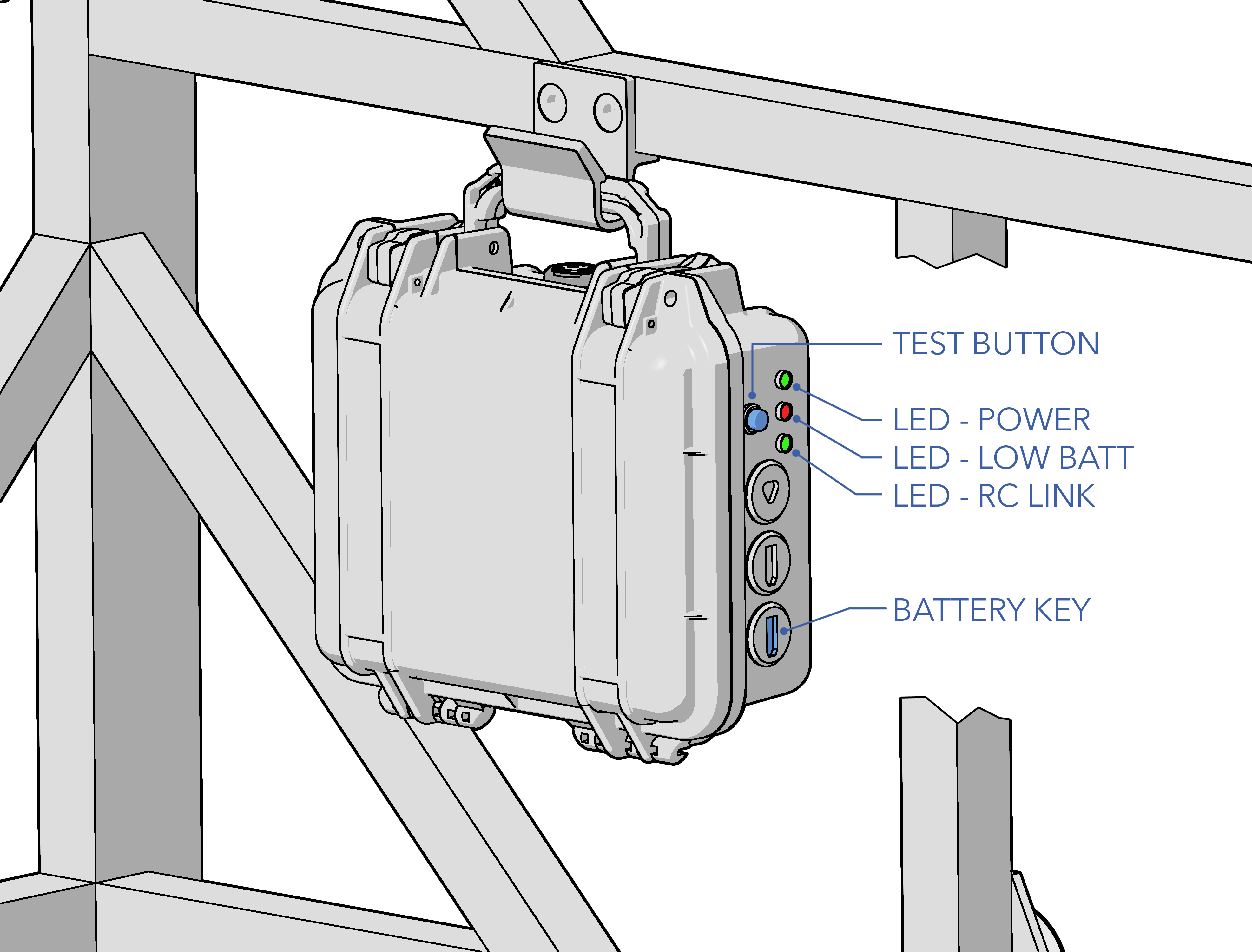
A low battery may fail to release the aircraft when commanded.
The launch receiver is bound to the hand controller and uses the internal 2.4Ghz RF module, not the RFD900 radio. If the RC link status LED does not illuminate:
- Verify the hand controller is powered on.
- Verify the hand controller model displays FLM136.
- Check the hand controller is bound to the release receiver. Only one controller can be bound to the receiver at a time.
- Verify the receiver is connected to the release box.
Release Solenoid - Test
Press the release button on the hand controller. The release solenoid should activate and open three times.
Launcher - Mount Aircraft
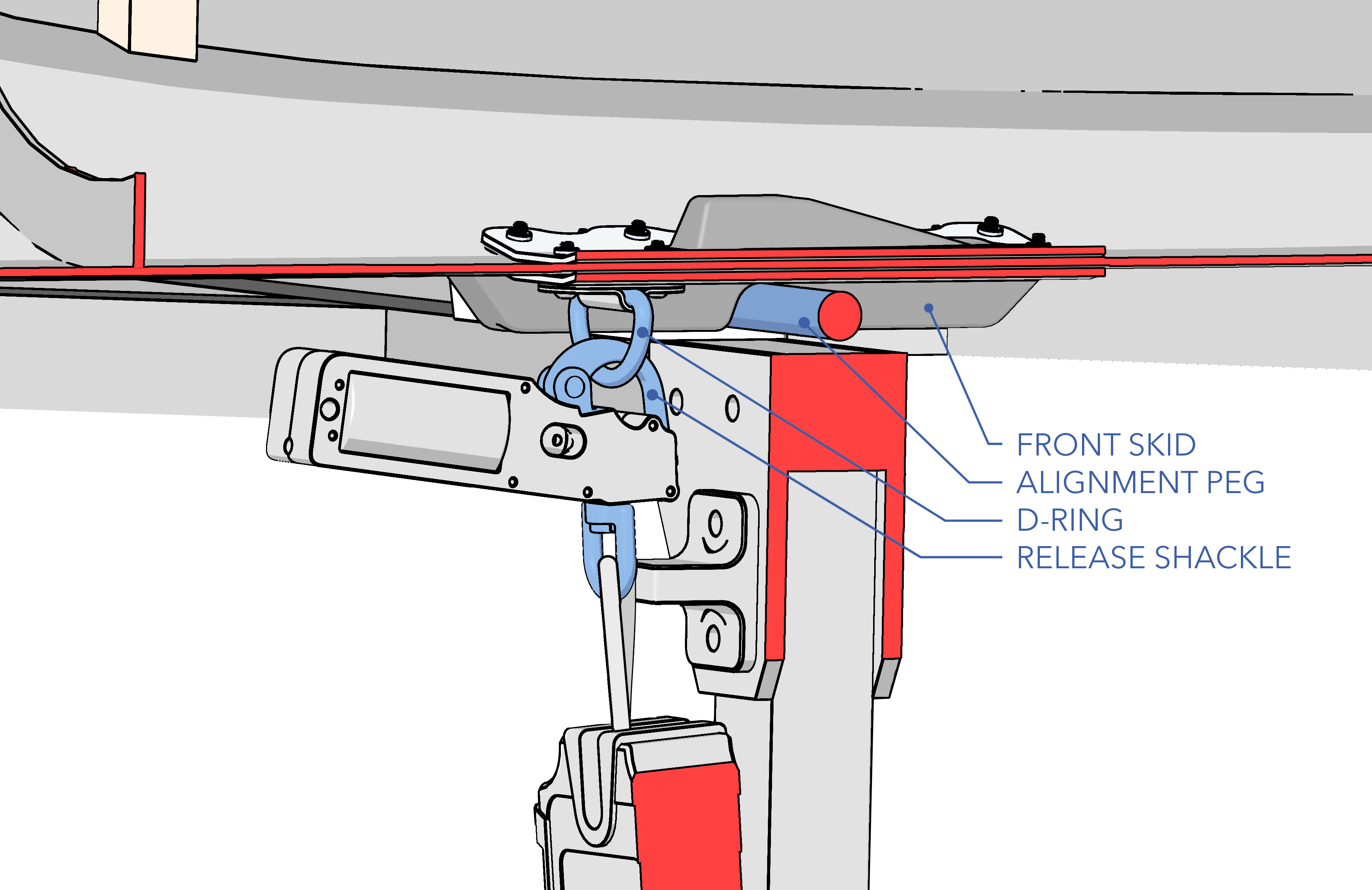
With the launcher lowered, mount the aircraft on the launcher. Center the aircraft on the foam cradles and slide it forward until the front skid catches the alignment peg.
Lifting the aircraft requires a minimum of two people, three is recommended.
Release Shackle - Secure
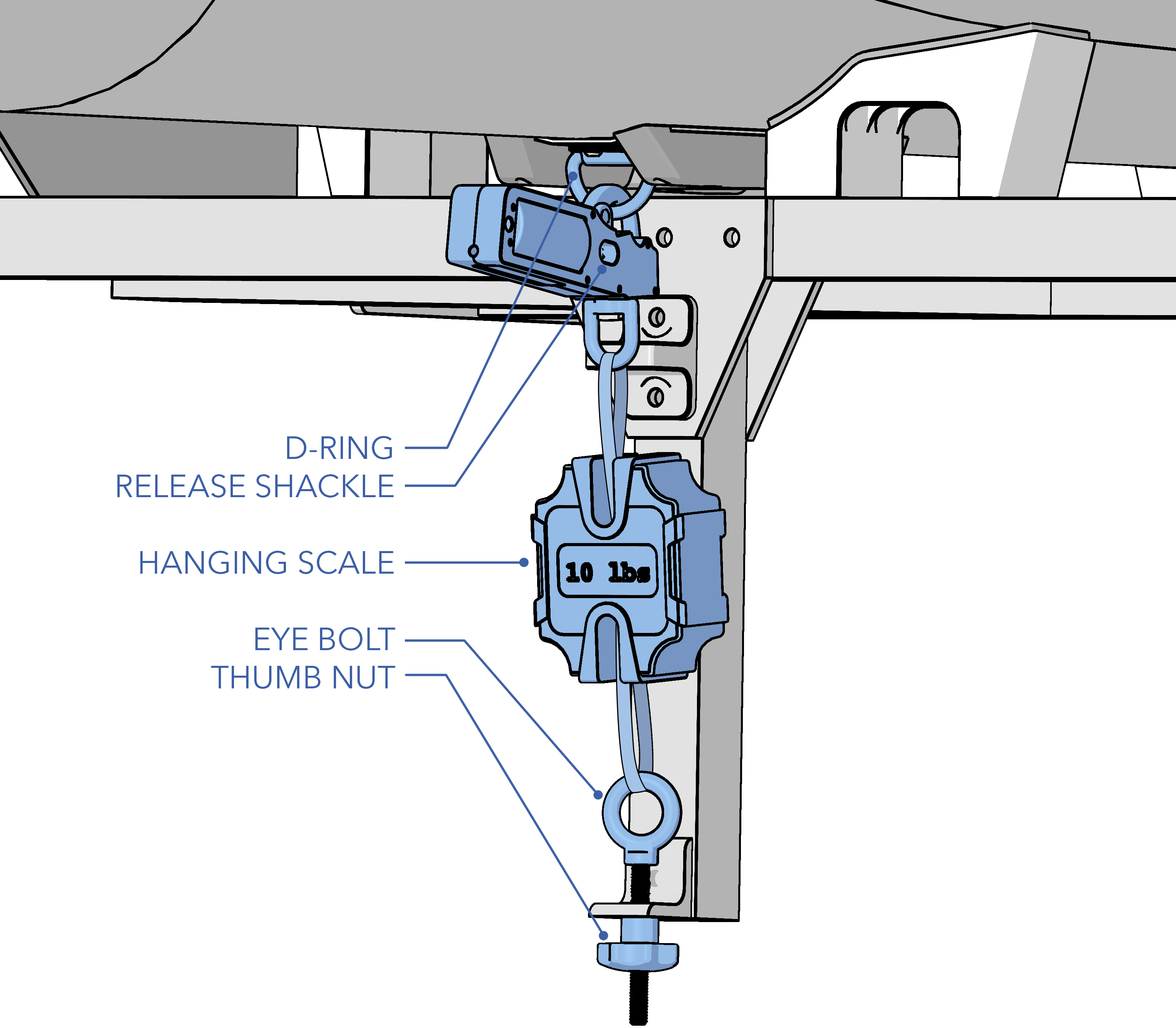
Secure the release shackle to the D-ring located on the underside of the fuselage. Ensure, when hooked up, that both the release solenoid and line scale face forward towards the front of the truck.
Release Tension - Set 10 lbs
Turn the line scale on and tare it with no tension. Tighten the thumb nut at the base of the eye bolt to apply tension until the scale reads 10 lbs.
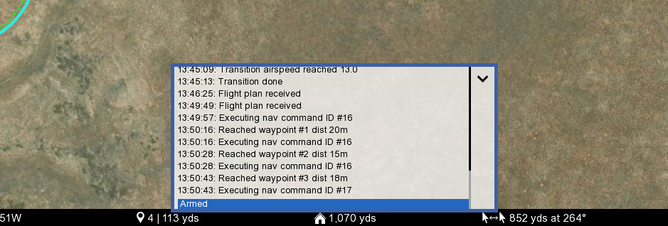
No Warnings - Verify
Ensure there are no warnings before takeoff. All warnings must be resolved. Warnings are displayed in the GCS message panel. Refer to the Warnings Section for a detailed description of warnings, possible causes, and corrective actions.
Engine - Prime
Prime the engine.
- Close the choke to restrict air to the engine.
- Turn the propeller by hand several times in both clockwise and counter-clockwise direction to draw fuel into the carburetor. Do not make full rotations of the propeller, but instead 'bounce' the propeller off the compression stroke in both directions.
- Watch for fuel movement in the fuel line. Fuel should advance towards the carburetor as you turn the propeller.
- Once fuel enters the carburetor inlet fitting, continue turning the propeller several more times.
- Open the choke and check for fuel on the valve. Fuel should bead or drip when you first open the valve. If you do not see any fuel, continue priming and check for drips after every few turns of the propeller.
- Close the choke.
- The engine is now primed and ready. If the aircraft sits for a few minutes, it may need to be primed again.
Aircraft - Arm
Press Arm on the checklist step to arm the aircraft.
Before arming, the aircraft must undergo a series of automated pre-arm checks, which are distinct from preflight checks and are performed internally by the autopilot. Failed pre-arm checks will be displayed in the message panel of the GCS. See Arming Checks for a detailed description of pre-arm checks, possible causes, and corrective actions.
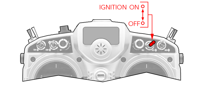
Ignition - On
Using the hand controller, set the ignition switch to on.
Engine - Start
Stand behind the truck launcher on the ground and manually start the engine using either hand-propping or a starter motor. Begin with the choke closed, cranking the engine until it "pops." Then, open the choke and proceed to start the engine. Ensure all personnel are clear of the propeller arc, as it may take a few attempts to start, especially in cold weather.
Starting the engine rotates the propeller. Rotating propellers can cause serious injury or death. Ensure all personnel are clear of the propellers.
Engine parts, especially the muffler, will be extremely hot while running. Burns can occur on contact. Keep flammable materials away from the engine.
Engine - Warmup
Allow the engine to warm up at idle for at least one minute.
Full Throttle RPM - Verify
Ensure someone is bracing the front of the fuselage before advancing to full throttle. Using the hand controller, raise the throttle to full and hold for 7-10 seconds. The engine should not hesitate or bog down when throttle is advanced. The RPM should be between 5,200 to 5,700.
Idle RPM - Verify
Using the hand controller, lower the throttle to idle. The RPM should be between 2,500 - 3,000.
Launcher - Raise
Raise the launcher using the winch. Once upright, tighten the winch to prevent the cable from coming loose on the pulleys.
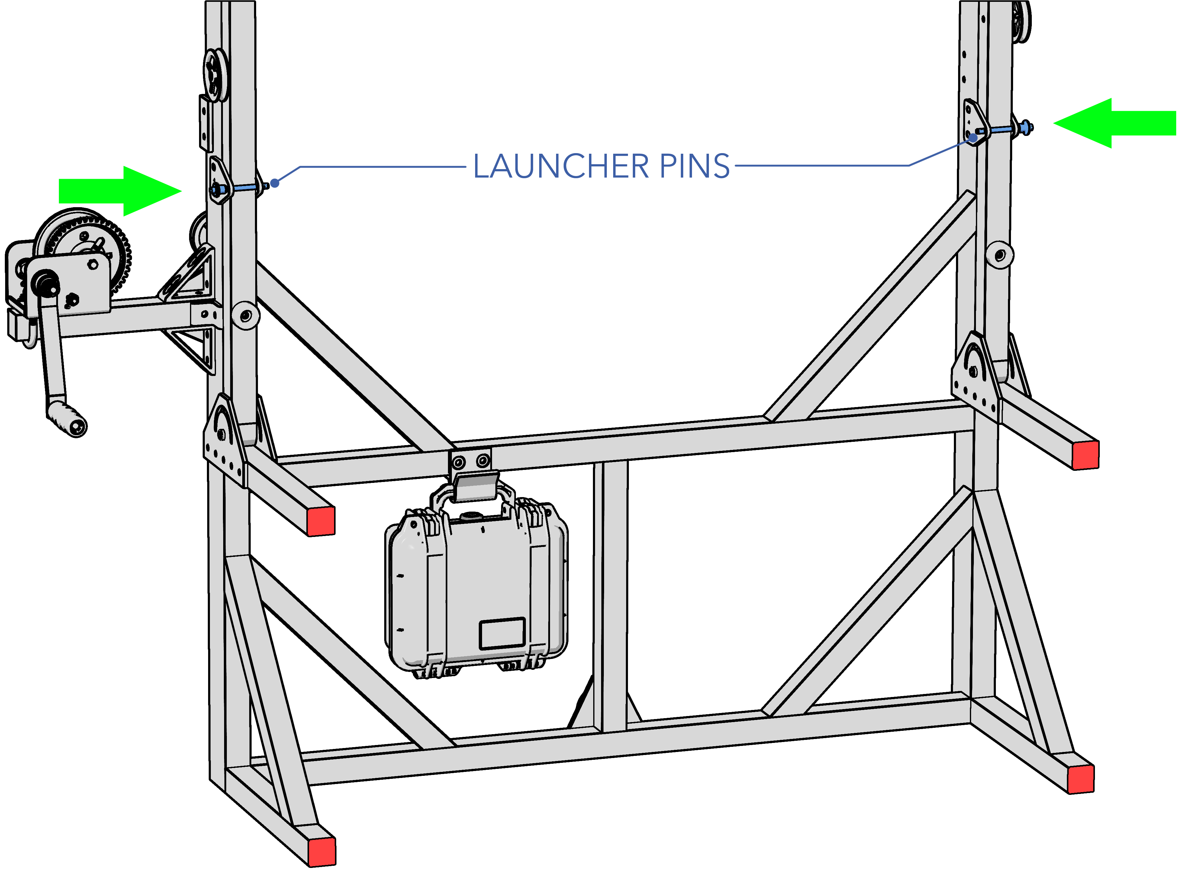
Launcher Pins - Install
Insert both launcher pins to secure the launcher in its upright position.
Truck - Taxi to Runway
The driver proceeds to the start of the runway.
Takeoff Heading - Establish
Ensure the driver is facing the direction of takeoff.
Release Tension - Verify 10 lbs
The driver verifies that the line scale still reads 10 lbs, or adjust its accordingly.
No Warnings - Verify
Ensure there are no warnings before takeoff. All warnings must be resolved. Warnings are displayed in the GCS message panel. Refer to the Warnings Section for a detailed description of warnings, possible causes, and corrective actions.
Begin Takeoff - Announce
Announce to the driver to commence the takeoff roll.
Throttle 75% - Raise at 50 mph
Using the hand controller, the safety pilot raises the throttle to 75% when the truck has passed 50 mph (43 knots).
Pitch Up 75% - Hold at 50 mph
Using the hand controller, the safety pilot holds pitch up when the truck has passed 50 mph (43 knots).
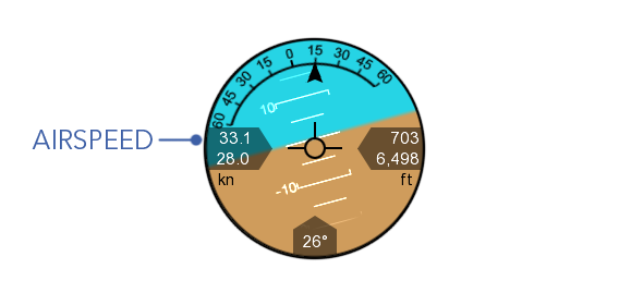
Takeoff Speed - Establish 75 mph
Confirm that the driver is traveling at 75 mph (65 knots) or greater using the airspeed reading on the HUD.
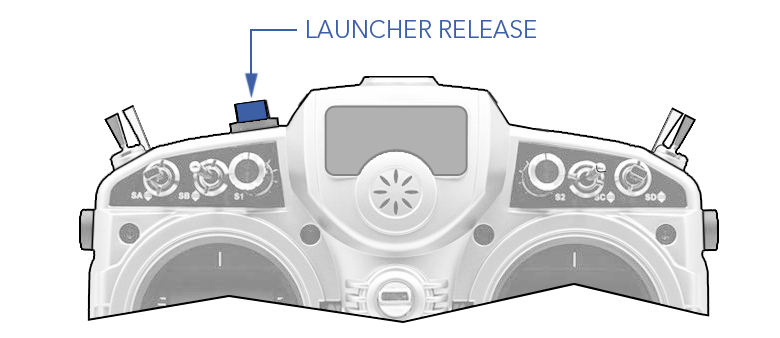
Aircraft - Release
Using the hand controller, the safety pilot presses the release button when the aircraft is at a comfortable distance and within clear line of sight.
Aircraft Clear - Announce
Announce to the driver when the aircraft is clear of the launcher.